Monday 30 May 2011

MODEL DRAWINGS

Now time to include measurements and model drawings.

CHAIR MEASUREMENTS

ANGLE MEASUREMENTS

DRILL HOLE PLACEMENT

The final model will be made from cut, bent and welded 19mm tubular steel. 

New concept

I decided to draw a bit on an earlier idea I had during concept stage to use a "jigsaw" style frame. This will eliminate the use of sleeves and provide an extra point of interest. I want to use large, chunky bolts to give the design an industrial type feel.

This is the earlier developed frame shape from which I gathered inspiration.

I then developed some quick solidworks models, to help visualize how the pieces will fit together.
This new design will allow for easy disassembly and minimal welding.

New frame's elevation views.
PLAN VIEW


SIDE VIEW


FRONT VIEW


BACK VIEW

Chair frame exploration

After deciding that I needed a new idea for the chair frame, I decided to get a flat pack chair from Ikea and explore the construction methods used in their chair.


  After making the Ikea chair, I realised that I'm really going to need to use bolts or screws somewhere in my design. Doing this makes it relatively simple to assemble. At this stage I might also explore incorporating another idea that I developed in the concept stage.

Initial 1:1 scale drawing

A 1:1 drawing was developed for ergonomic checking.
I still wasn't 100% happy with the very simple frame. I also don't really like the sleeving idea, as it may make the frame look a bit messy and jeopardize the structural integrity of the design.

Initial solidworks model

Then I developed a solidworks model of the simple chair frame.
 At this stage, attention needed to be given to materials and manufacturing. The model will require either 19mm or 25mm steel tube (available from Bunnings) with the processes of bending, cutting, and welding.

In order for the model to fit in the specified box, the legs will need to be removable. Ideally these would be screw off, but more likely sleeves for the legs will need to be made.

DEVELOPMENT

After developing my scale mockup I decided that the frame shape still wasn't right. I went back to the drawing board to find a frame I was happy with.

After much deliberation I decided to stick to a very basic frame, and leave the detail in the rope weaving.
I also had a look at how it will all come together with the rope pattern.

Initial 1:5 mockup

After deciding on a chair frame shape, I experimented through the development of a mockup.


DEVELOPMENT

The development of my design started with exploration of frame types and ergonomic features

 My next hurdle was deciding how to attach the rope to my chair. The main techniques I was interested in exploring were using a crochet technique around the pole, wrapping the rope around the pole, attaching a zig zag wire feature to the pole, drilling holes into the pole and sewing a sleeve with eyelets in it over the top.
The next step is to work out materials and the pattern to make with the rope.

Experimentation with knotting the rope around a pole

After deciding on a knotting technique, I then moved on to develop a frame. I wanted it to be relatively simple in form with a deep set back. This is the initial chair frame shape I came up with.
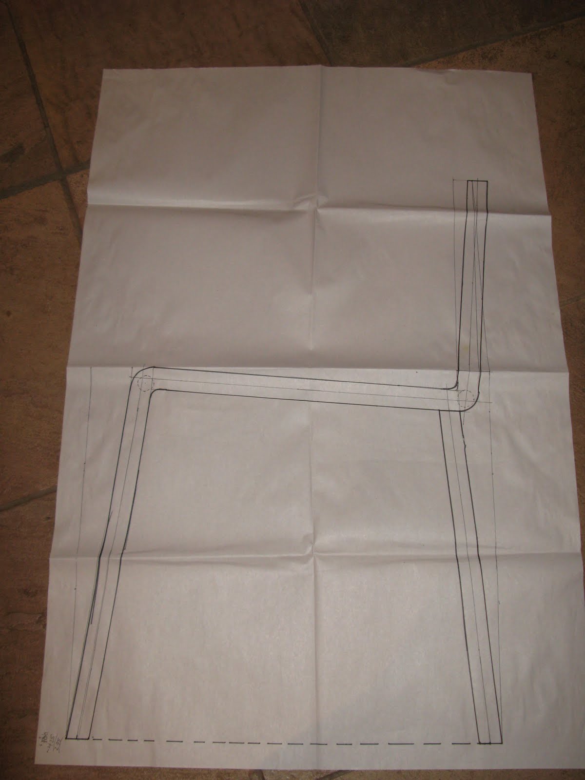
Rope chair exemplar images

After deciding to proceed with the rope chair concept, I did some research into existing designs to gather inspiration.